Flight Instruments: Attitude and Heading Indicator
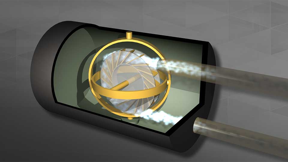
Flight Instruments: Attitude and Heading Indicator
Training Notes: Flight Instruments - Attitude and Heading Indicator
This section covers the operation of air-driven attitude and heading instruments, focusing on the vacuum and pressure systems, potential failures, and how to manage related errors.
Vacuum and Pressure Systems
- Air-driven gyroscopic instruments (attitude and heading indicators) are often called vacuum instruments.
- They rely on a pressure differential between ambient air and pressure inside the instrument case.
- The gyros are spun by air striking the vanes of the rotor.
Types of Vacuum Systems
- Vacuum-driven systems:
- A partial vacuum is created inside the instrument case.
- Air rushes into the case through nozzles, spinning the gyro rotor.
- Pressure-driven systems:
- Air under pressure is pumped into the instrument case through nozzles.
- Common in twin-engine and pressurized aircraft.
- Positive pressure needed for systems like deicing boots.
- Most light single-engine aircraft use vacuum pumps to reduce pressure inside instrument cases.
System Components
- Relief valves to control pressure and vacuum levels.
- Air filters to ensure clean air enters the system.
Importance of Monitoring Vacuum Systems
- Regularly check the vacuum gauge during instrument scan.
- A low vacuum warning light is even better for immediate awareness.
- Maintenance of vacuum pumps:
- Most dry vacuum pumps have a life limit of 500-1,000 flight hours or six years.
- Pumps used for deicing boots may have shorter life limits (as low as 300 hours).
- Replace the pump if the engine experiences sudden stoppage.
- Backup systems are important due to difficulty flying without these instruments:
- Some aircraft are required to have dual pumps.
- Standby systems include:
- Dual vacuum pumps operating continuously.
- Electric pumps that activate when needed.
- Systems using reduced engine intake manifold pressure to remove air from gyro cases.
Precession and Attitude Indicator Errors
- Precession causes errors in the attitude indicator, corrected by the erection mechanism.
- Acceleration and deceleration errors:
- Acceleration causes the horizon bar to move down, indicating nose-up attitude.
- Deceleration causes the horizon bar to move up, indicating nose-down attitude.
- Errors during turns:
- After skidding turns, leveling the wings may show a 3-5 degree opposite bank.
- Coordinated turns cause precession errors related to turn amount and bank angle.
- Maximum error occurs during 180-degree turns.
- Errors cancel out over 360-degree turns.
- These errors typically last less than 15 seconds.
Glass Cockpit Systems
- Glass-equipped aircraft may or may not have vacuum systems.
- Some have basic vacuum systems for backup attitude indicators.
- Primary Flight Displays (PFDs) use Attitude Heading Reference Systems (AHRS).
- AHRS is electrically driven.
- Uses internal sensors, accelerometers, GPS, and airspeed data to determine attitude.
Understanding how vacuum and pressure systems work, and recognizing potential errors in your instruments, is crucial for safe and effective flying.